
南科大詹陈长团队合作提出一种峰值效率97.6% 的Buck-Boost混合转换器

教育热点|2023-11-27 13:39:29|阅读量:1169
<p style="box-sizing: border-box; margin-bottom: 0px; text-indent: 2em; text-align: justify; color: rgb(34, 24, 21); font-family: 微软雅黑; background-color: rgb(255, 255, 255);"><span style="font-size: 14px;"><br>
</span></p>
<p style="box-sizing: border-box; margin-bottom: 0px; text-indent: 2em; text-align: justify; color: rgb(34, 24, 21); font-family: 微软雅黑; background-color: rgb(255, 255, 255);"><a href="https://uconf.com/" target="_blank">爱科会易</a><span style="font-size: 14px;">从南方科技大学官网获悉,近日,南方科技大学深港微电子学院副教授詹陈长和澳门大学微电子研究院副教授路延团队合作在电源管理芯片研究的重要分支—DC-DC转换器芯片设计领域取得重要进展,双方联合培养的博士生赵双星提出了一种峰值效率97.6% 的Buck-Boost混合转换器。相关论文成果以“A Battery-Input Three-Mode Buck-Boost Hybrid DC-DC Converter with 97.6% Peak Efficiency”为题发表在集成电路设计领域顶级期刊《固态电路杂志》(IEEE Journal of Solid-State Circuits, JSSC)上。</span><br>
</p>
<p style="box-sizing: border-box; margin-bottom: 0px; text-indent: 2em; text-align: justify; color: rgb(34, 24, 21); font-family: 微软雅黑; background-color: rgb(255, 255, 255);"><br>
</p>
<p style="box-sizing: border-box; margin-bottom: 0px; text-indent: 2em; text-align: justify; color: rgb(34, 24, 21); font-family: 微软雅黑; background-color: rgb(255, 255, 255);"><img src="https://newshub.sustech.edu.cn/uploads/full/2023/11/021698907604729612.png" title="021698907604729612.png" alt="微信图片_20231102144620.png" style="box-sizing: border-box; border: 0px; vertical-align: middle; max-width: 600px; height: auto !important; margin: 6px auto; display: block;" width="500"></p>
<p style="box-sizing: border-box; margin-bottom: 0px; text-indent: 2em; text-align: justify; color: rgb(34, 24, 21); font-family: 微软雅黑; background-color: rgb(255, 255, 255);"><br>
</p>
<p style="box-sizing: border-box; margin-bottom: 0px; text-indent: 2em; text-align: justify; color: rgb(34, 24, 21); font-family: 微软雅黑; background-color: rgb(255, 255, 255);"><br>
</p>
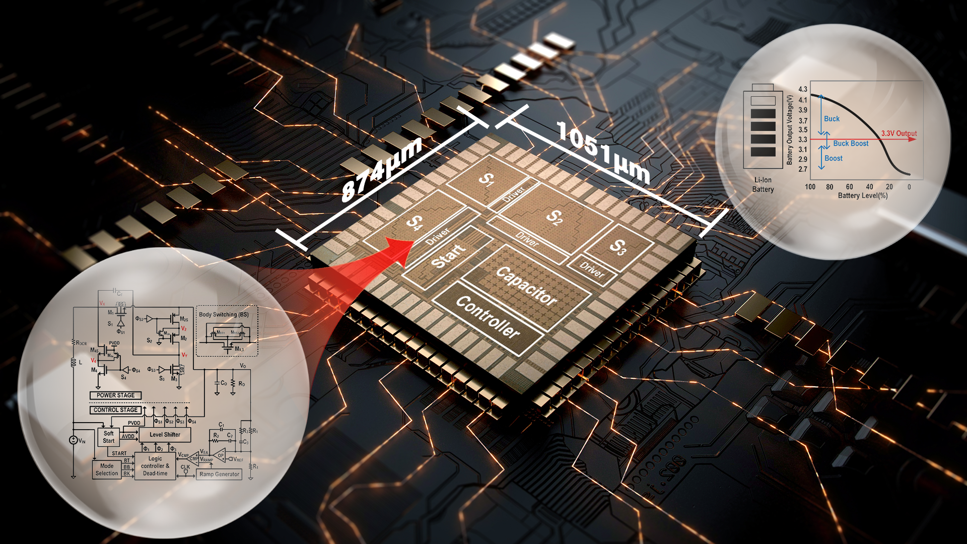
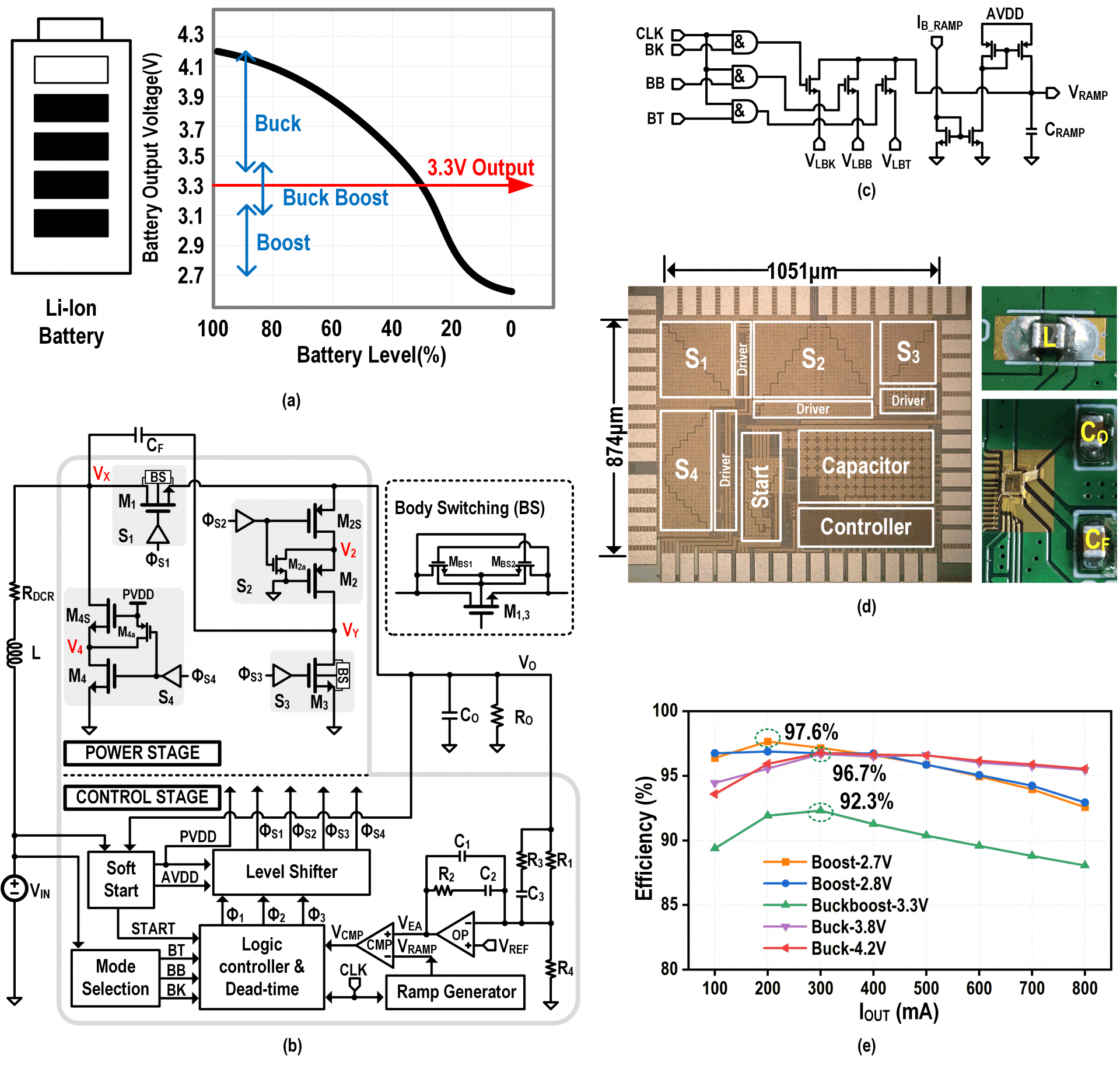
<p style="box-sizing: border-box; margin-bottom: 0px; text-indent: 2em; text-align: justify; color: rgb(34, 24, 21); font-family: 微软雅黑; background-color: rgb(255, 255, 255);"><span style="font-size: 14px;">当今社会,智能移动设备正在越来越多地影响我们的生活,这些设备大多选择锂离子电池作为电源,而这些设备中的大多数模块需要3.3 V电源,因此3.3V电压是电池PMIC的典型目标输出电压。但如图1(a)所示,锂电池的输出电压会随电量的变化而变化。所以,非反向的buck-boost成为一个好的选择。但是,传统的buck-boost需要两个开关管同时工作,会导致导通和开关损耗。同时,它的电感电流很大,也会有很大的导通损耗。一些工作通过多模式的buck-boost减少了损耗,但是在模式切换时,会有大的过冲或下冲电压的问题。为了解决以上问题,本工作提出了一个拥有三个工作模式的非反向buck-boost混合型转换器(3M-BBHC),以减少主路开关数量,降低电感电流的方式来提高效率,以动态的斜坡信号来实现平滑的模式切换。</span><br>
</p>
<p style="box-sizing: border-box; margin-bottom: 0px; text-indent: 2em; text-align: justify; color: rgb(34, 24, 21); font-family: 微软雅黑; background-color: rgb(255, 255, 255);"><span style="font-size: 14px;"><br>
</span></p>
<p style="box-sizing: border-box; margin-bottom: 0px; text-indent: 2em; text-align: justify; color: rgb(34, 24, 21); font-family: 微软雅黑; background-color: rgb(255, 255, 255);"><span style="font-size: 14px;"><br>
</span></p>
<p style="box-sizing: border-box; margin-bottom: 0px; text-indent: 2em; text-align: justify; color: rgb(34, 24, 21); font-family: 微软雅黑; background-color: rgb(255, 255, 255);"><img src="https://newshub.sustech.edu.cn/uploads/full/2023/10/311698719052859487.png" title="311698719052859487.png" alt="微信图片_20231031102312.png" style="box-sizing: border-box; border: 0px; vertical-align: middle; max-width: 600px; height: auto !important; margin: 6px auto; display: block;" width="500"></p>
<p style="box-sizing: border-box; margin-bottom: 0px; text-indent: 2em; text-align: center; color: rgb(34, 24, 21); font-family: 微软雅黑; background-color: rgb(255, 255, 255);"><span style="font-size: 14px;">图1. (a)锂电池输出电压随电池容量的变化 (b)本文提出的3M-BBHC的系统架构 (c)动态斜坡信号产生电路 (d)芯片照片 (e)不同输入电压下的测试效率&nbsp;</span><br>
</p>
<p style="box-sizing: border-box; margin-bottom: 0px; text-indent: 2em; text-align: center; color: rgb(34, 24, 21); font-family: 微软雅黑; background-color: rgb(255, 255, 255);"><span style="font-size: 14px;"><br>
</span></p>
<p style="box-sizing: border-box; margin-bottom: 0px; text-indent: 2em; text-align: center; color: rgb(34, 24, 21); font-family: 微软雅黑; background-color: rgb(255, 255, 255);"><span style="font-size: 14px;"><br>
</span></p>
<p style="box-sizing: border-box; margin-bottom: 0px; text-indent: 2em; text-align: center; color: rgb(34, 24, 21); font-family: 微软雅黑; background-color: rgb(255, 255, 255);"><span style="box-sizing: border-box; color: rgb(127, 127, 127);"><img src="https://newshub.sustech.edu.cn/uploads/full/2023/10/311698719077798401.png" title="311698719077798401.png" alt="微信图片_20231031102319.png" style="box-sizing: border-box; border: 0px; vertical-align: middle; max-width: 600px; height: auto !important; margin: 6px auto; display: block;" width="500"></span></p>
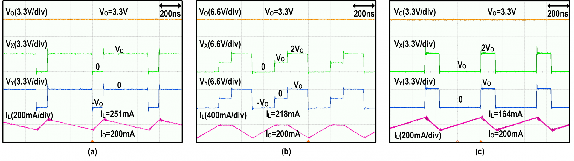
<p style="box-sizing: border-box; margin-bottom: 0px; text-indent: 2em; text-align: center; color: rgb(34, 24, 21); font-family: 微软雅黑; background-color: rgb(255, 255, 255);"><span style="font-size: 14px;">图2. 随输入电压变化,工作模式切换的瞬态响应测试图:(a)从boost到buck-boost,再到buck模式(b)从buck到buck-boost,再到boost模式</span><br>
</p>
<p style="box-sizing: border-box; margin-bottom: 0px; text-indent: 2em; text-align: center; color: rgb(34, 24, 21); font-family: 微软雅黑; background-color: rgb(255, 255, 255);"><span style="font-size: 14px;"><br>
</span></p>
<p style="box-sizing: border-box; margin-bottom: 0px; text-indent: 2em; text-align: center; color: rgb(34, 24, 21); font-family: 微软雅黑; background-color: rgb(255, 255, 255);"><span style="box-sizing: border-box; color: rgb(127, 127, 127);"><img src="https://newshub.sustech.edu.cn/uploads/full/2023/10/311698719092405337.png" title="311698719092405337.png" alt="微信图片_20231031102325.png" style="box-sizing: border-box; border: 0px; vertical-align: middle; max-width: 600px; height: auto !important; margin: 6px auto; display: block;" width="500"></span></p>
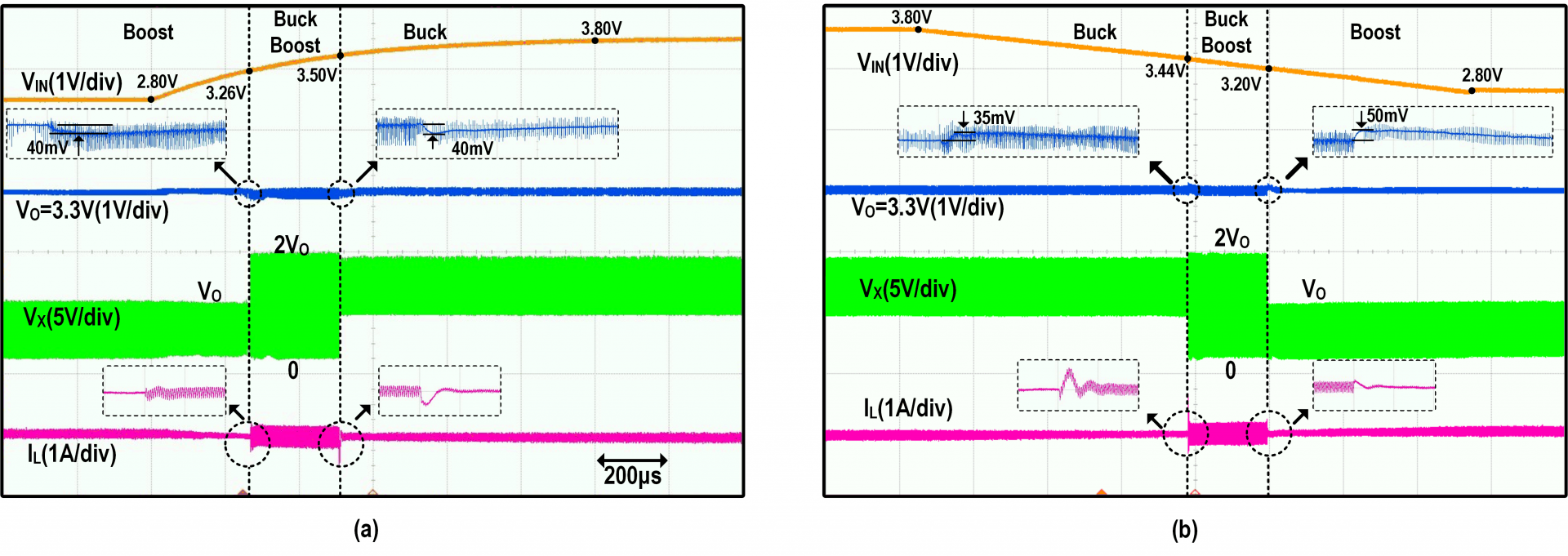
<p style="box-sizing: border-box; margin-bottom: 0px; text-indent: 2em; text-align: center; color: rgb(34, 24, 21); font-family: 微软雅黑; background-color: rgb(255, 255, 255);"><span style="font-size: 14px;">图3.不同工作模式下,测量的输出电流为200 mA的稳态波形:(a)2.7V输入电压的boost模式,(b)3.3V输入电压的Buck-Boost模式,(c)4.2V输入电压的buck模式&nbsp;</span></p>
<p style="box-sizing: border-box; margin-bottom: 0px; text-indent: 2em; text-align: center; color: rgb(34, 24, 21); font-family: 微软雅黑; background-color: rgb(255, 255, 255);"><span style="font-size: 14px;"><br>
</span></p>
<p style="box-sizing: border-box; margin-bottom: 0px; text-indent: 2em; text-align: center; color: rgb(34, 24, 21); font-family: 微软雅黑; background-color: rgb(255, 255, 255);"><span style="font-size: 14px;"><br>
</span></p>
<p style="text-align: justify; box-sizing: border-box; margin-bottom: 0px; text-indent: 2em; color: rgb(34, 24, 21); font-family: 微软雅黑; background-color: rgb(255, 255, 255);" align="left"><span style="font-size: 14px;">&nbsp;如图1(b)所示,这项工作提出了一种拥有三个模式的非反向buck-boost混合转换器(3M-BBHC)。它包括控制模块,功率模块和片外的电感,飞电容,输出电容。为了减少芯片面积和寄生电容,在所有电路模块中仅使用3.3V器件。功率模块由四个开关S1,2,3,4组成。在图2的底部,控制电路包含了斜坡信号发生模块,逻辑控制模块,模式选择模块,软启动模块,死区时间生成模块和电平转换模块。该3M-BBHC可以平滑地在buck、boost或buck-boost模式下切换;在保持四功率开关的前提下添加了飞电容(CF);将与电感串联的功率管数量从两个(CBBC)减少到1个(3M-BBHC),以减小了导通和开关损耗;将电感放到输入端,在保持3M-BBHC具有连续的输入电流的前提下获得较小的EMI。此外,在buck模式下,其电感电流总是小于输出电流,这会降低电感直流电阻(DCR)的导通损耗。

如图1(c)所示,为了提高模式切换的性能,本文提出了一个动态斜坡产生电路。图2展示了随输入电压变化,工作模式切换的瞬态响应测试图。可以看到,3M-BBHC实现了平滑的模式切换。图3展示了三个工作模式的稳态波形。图1(d)和图1(e)分别展示了芯片照片和不同输入电压下的测试效率。本文实现了最高97.6%的效率。

南科大—澳门大学联合培养博士生赵双星是论文的第一作者,詹陈长和路延为上述论文的共同通讯作者,南科大为论文第一单位。本项目研究获得了国家自然科学基金委,深圳市科创委,澳门特别行政区科技发展基金以及企业横向课题的经费资助。</span></p>
<p style="text-align: justify; box-sizing: border-box; margin-bottom: 0px; text-indent: 2em; color: rgb(34, 24, 21); font-family: 微软雅黑; background-color: rgb(255, 255, 255);" align="left"><span style="font-size: 14px;"><br>
</span></p>
<p style="text-align: justify; box-sizing: border-box; margin-bottom: 0px; text-indent: 2em; color: rgb(34, 24, 21); font-family: 微软雅黑; background-color: rgb(255, 255, 255);" align="left"><span style="font-size: 14px;">&nbsp;论文链接:https://ieeexplore.ieee.org/document/10281380&nbsp; &nbsp; &nbsp;</span><br>
</p>
<p style="text-align: justify; box-sizing: border-box; margin-bottom: 0px; text-indent: 2em; color: rgb(34, 24, 21); font-family: 微软雅黑; background-color: rgb(255, 255, 255);" align="left"><span style="font-size: 14px;"><br>
</span></p>
<p style="text-align: justify; box-sizing: border-box; margin-bottom: 0px; text-indent: 2em; color: rgb(34, 24, 21); font-family: 微软雅黑; background-color: rgb(255, 255, 255);" align="left"><span style="font-size: 14px;">来源:南方科技大学官网</span></p>